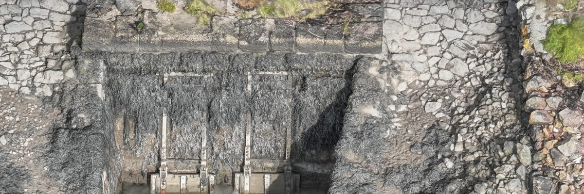
Aerial view of the tidal river embankment along the River Barrow in County Wexford

Embankment inspection in County Wexford

Two kilometres of tidal river embankment on the River Barrow, mapped end to end into a 3D model, a face-on orthophoto and AutoCAD line work.
Overview

The Job at a Glance

A drone photogrammetry survey of roughly two kilometres of the Kilmannock Embankment on the River Barrow in County Wexford, delivering a high-resolution 3D model, a face-on orthophoto and AutoCAD line work so the client could plan remedial works on every defect found.

Two kilometres of tidal embankment

The Kilmannock Embankment, on the River Barrow in County Wexford, facing the tidal river and close to a power station.

Captured at the lowest tide

Flown at the lowest astronomical tide so the full structure was visible above the water.

Ground control and scale references

Ground control points along the full length, plus known-size constraining elements to scale the 3D model precisely.

3D model, orthophoto and line work

A photogrammetric 3D model, a face-on orthophoto at around five millimetre GSD, and AutoCAD line work of every defect.

Background

Two kilometres of tidal river embankment

The Kilmannock Embankment runs along the River Barrow in County Wexford, facing roughly two kilometres of tidal water. Depending on the tide, some sections face onto mudflats and some face onto the river itself, and because the flow and the tide affect different areas to different degrees, some sections had deteriorated more than others.

The structures had been inspected by traditional means a few years earlier, by walking the full length looking for problems. The client wanted them re-surveyed so a scope of works could be put in place for remedial repairs before the embankments deteriorated any further. Where water is involved, a small defect can become a major issue very quickly, and a flood of salt water could compromise the land the embankments are protecting.

The challenge

Accessible from the air, difficult from land

Because the embankments are long and linear, and easy to reach from the air but very difficult to access from land, the drone was chosen as the best solution for inspecting them.

Before going to site, the team held planning meetings with the client to lock down the scope: the level of detail required, the types of defects to look for, and confirmation that the drone could resolve those defects in the captured data. How much vegetation was growing over the embankments was a key part of that decision.

Methodology

Capturing the full structure at the lowest tide

The survey was timed to the lowest astronomical tide so that the entire structure was visible; at high tide much of it would have been underwater.

Ground control was laid out along the full length of the embankment, with constraining elements of known vertical and horizontal size placed in the scene so the 3D model could be scaled correctly. The flights then captured the embankments in three phases, in low and high resolution, using oblique and nadir imagery with proper photogrammetric overlap, along with broad orientation imagery and detailed imagery.

The data was processed into the deliverables and quality checked before it was presented to the client.

Deliverables

A measurable 3D model, orthophoto and line work

The client received a complete, measurable record of the embankments, ready to open in AutoCAD or any GIS platform.

High-resolution 3D model

A photogrammetric scan of the full embankment at around one centimetre ground sampling distance, clear enough to tell new concrete from old, missing stones, cracks, sinkholes and lost material.

Face-on orthophoto

Because the embankment sits at 30 to 40 degrees, the orthophoto was generated perpendicular to its face rather than nadir, at around five millimetre GSD.

AutoCAD line work

Every defect area overlaid onto the orthophoto as vectorised, classified line work, so the client could quantify the area of embankment in trouble.

Top-down plan view of the full surveyed embankment showing the orthophoto sheet layout
An overall top-down plan view of the full surveyed embankment, illustrating the layout and boundaries of the individual orthophoto sheets.
Scaled orthomosaic sheets of the embankment face with defect areas outlined
The embankment face drawn as scaled orthomosaic sheets, with each defect area outlined and quantified.
Orthophoto sheets of the embankment with the defect overlay and legend
Orthophoto sheets covering the full length of the embankment, delivered with the defect overlay for planning and estimation.
Detailed 3D view of a specific section of the embankment
A detailed 3D view of a specific section of the embankment, capturing the structure in one measurable record.
Interactive 3D model

Explore the embankment in 3D

The client found the 3D model incredibly intuitive and useful. Instead of bringing people out to the asset, the asset was brought to the people: anyone could open the model in a meeting, orientate themselves immediately, and see the scale and location of every problem before deciding where to concentrate effort.

The video below is a short sample extract from the full walkthrough of the interactive 3D model, giving a sense of how the surveyed structure can be explored and measured. The complete model is hosted online and can be opened on any device, so it can be interrogated remotely from a desktop, tablet or phone.

A short sample extract from the full 3D model walkthrough. The complete model is hosted online and can be explored and measured from any device, wherever you are.

Each phase of the model can also be opened and explored in full:

Comparative methodology

Why a drone made sense here

The embankments had been walked a few years earlier, but this time the client needed a measurable, geo-referenced record of every defect. The drone was chosen because the structures were easily reached from the air but very difficult to access from land.

Access
Surveyed from the air vs difficult to access from land

The embankments were easily accessible from the air but very difficult to reach from land, which is why the drone was chosen.

Detail
Five millimetre face-on orthophoto vs a visual walkover

The orthophoto resolved detail down to about five millimetres on the embankment face, and the 3D model to about one centimetre.

Deliverable
3D model plus AutoCAD line work vs notes from a walkover

Every defect was overlaid as vectorised line work so the client could quantify the embankment area in trouble in AutoCAD or GIS.

Efficient option Our method

Using a drone

A photogrammetry survey of the full embankment, flown at the lowest tide to capture the entire structure in one measurable record.

  • Chosen for a long, linear structure The drone was the best solution because the embankments were easy to reach from the air but hard to access from land.
  • Full high-resolution 3D model A photogrammetric scan of the entire embankment at around one centimetre GSD.
  • Face-on orthophoto Generated perpendicular to the embankment face at around five millimetre GSD, capturing far more detail than a nadir image.
  • AutoCAD line work Every defect overlaid and classified so it could be measured and quantified.
  • Captured at the lowest astronomical tide Flown when the whole structure was visible, so nothing was hidden by the water.
Project status Completed — 3D model, orthophoto and line work delivered
Manned approach Traditional method

Without a drone

The traditional method was to walk the full length of the embankment looking for problems, a few years after the last walkover had been carried out.

  • Walking the full length The traditional method meant walking the entire embankment looking for problems.
  • Difficult land access The structures were far easier to reach from the air than from the land.
  • A visual record, not a measurable dataset A walkover documents what the surveyor sees, where the drone delivered a scaled 3D model, a face-on orthophoto and quantified line work.
Operational impact Hard to access from land, with no measurable dataset
Let's talk

Speak to an engineer about your project

Complex surveys and inspections require more than just a pilot. Our engineers can help you scope your requirements and indentify the right approach.

Talk to an engineer

+353 (0)21 202 8281

Quickest for technical scoping

Email your brief

info@engineerswithdrones.ie

Best for sending detailed specs

Next steps

Where to find out more

You can find out more about our rivers and waterways inspections and our 3D mapping and photogrammetry services, or read about the tidal flood defence barrage aerial data collection case study. Alternatively, you can contact us here.

Last updated: